New cabin floor for sailboat Oceaan 25
Background
Good friends of mine bought a sailing boat of the type Oceaan 25 last year. Although the boat was in a good condition, there were a few
repairs necessary. Among other things, the floor in the cabin had to be replaced, which is made of plywood panels.
Since I assume that other Oceaan 25 owners might also have similar problems, I decided to publish the CAD data free of charge, so that everyone with access to a CNC router can produce a new floor. Of course I don’t guarantee a perfect fit, because between the boats of the type Oceaan 25 the dimensions may differ.
GIF-Animation of the floor plates 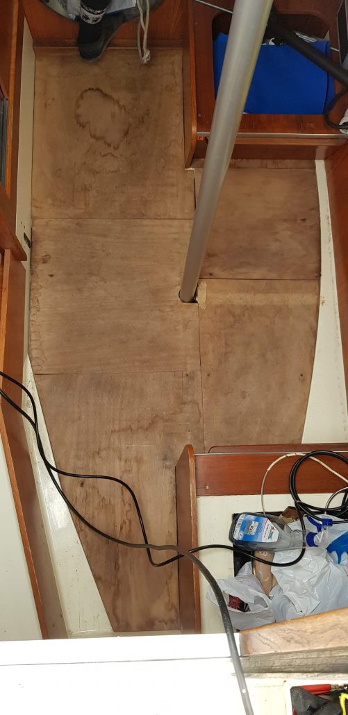
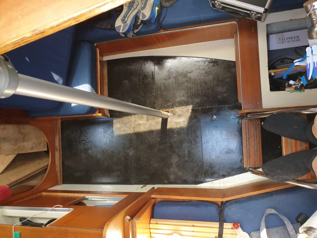
the old floor
Problem
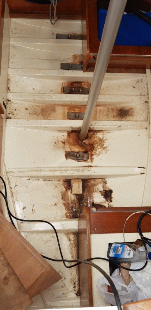
The floor in the cabin consists of a total of 6 different plywood panels. These panels were partially damaged by water and other panels were broken. All panels had in common that they became soft over the decades of use. Probably the wood fibres were at the end of their life, or the glue holding the layers together had softened. Either way, when you walked on the boards, it cracked and the boards bent. There was also a lot of play between the individual floor panels, so that the floor slipped back and forth and clattered when sailing at an list angle.
Project
It would’ve probably been possible to simply use the old plates as a template. However, one would then have had to use a jigsaw to cut out the plates. Some people are probably able to make perfectly straight cuts with a jigsaw – I am not one of these people. In addition some changes should also be made to the shapes and the play between the plates needed to be significantly reduced. Due to the desired precision of the parts we decided to cut the parts with a CNC router.
Also in the interior parts of a cabin of a boat, almost no right angles exist, this also applies to the floor.
As a Tailor by trade, my friend Suski, who also owns the boat, has some experience in drawing irregular shapes. She therefore took the initial measurements and made drawings of each individual floor plate in Autodesk Fusion 360. Together we then checked each measurement at a second day and at the spots, where we wanted to move a seam, or where we wanted to reduce the play, we made changes to the CAD data.
The original plates had a thickness of about 9mm. To increase the stability, we made the new floor from 12mm plywood. Since the floor is pushed under other furniture in two places, the thickness of the boards had to be reduced to 9mm at these spots.
Realization
I manually arranged the CAD data of the individual plates on a plate measuring 2.50 x 1.25m and then created a machine path for each of the individual work steps.
They were:
- Marking of the screw holes for fastening the plate on the machine
- Milling out the pockets
- Milling out the contours
After machining, the edges had to be sanded and some torn out areas had to be filled with filler before the floor slabs were sealed with waterproof paint.
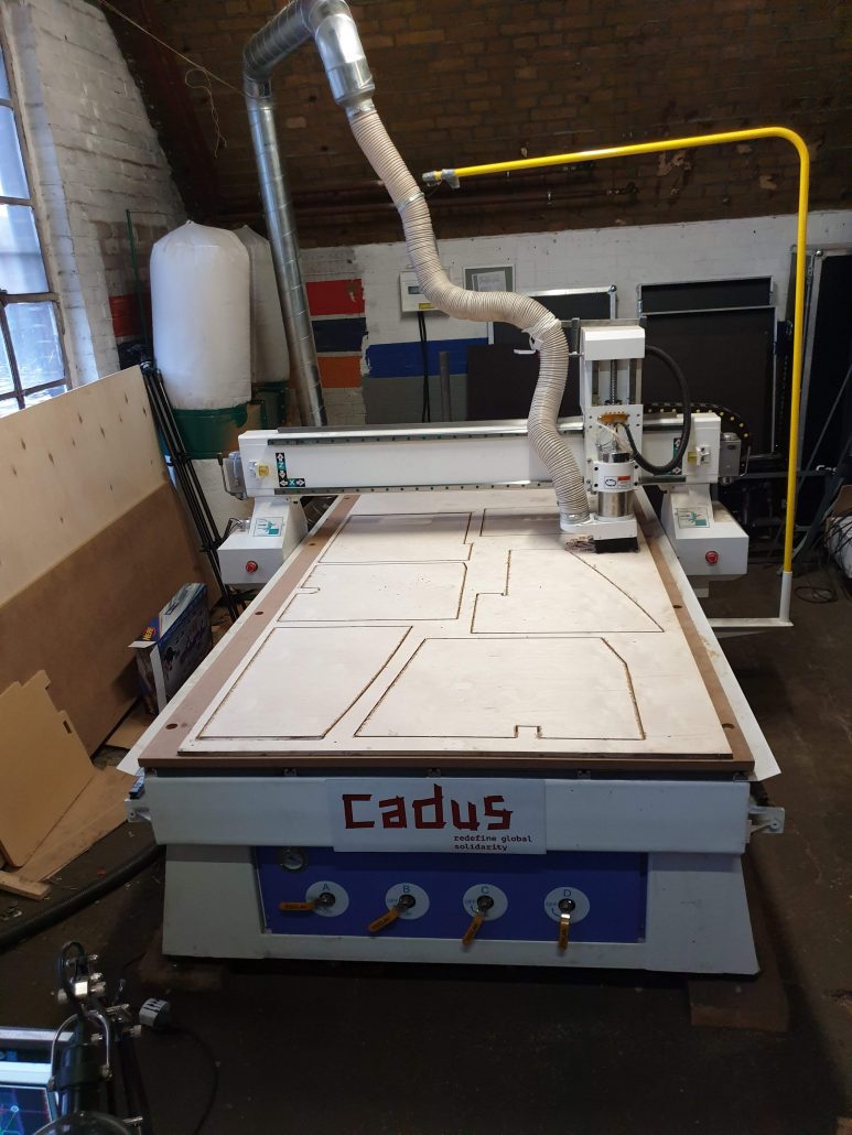
Routing of the parts 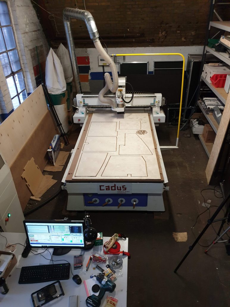
Routing of the parts with Computer 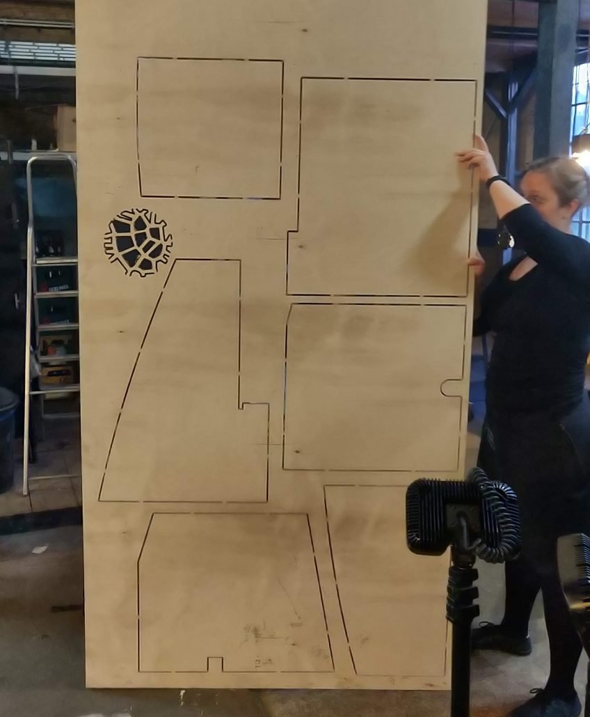
After routing 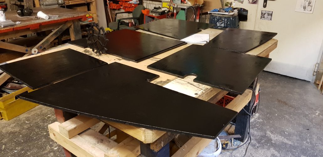
After Sanding, Filling and Painting
During installation, a few places appeared where the plates did not fit perfectly – fortunately the plates were too large rather than too small at these places – these places were corrected in the CAD model.
Success
The new floor fits very well and doesn’t clatter when you step on it, nor when you sail with a list. I made a video of the whole project, which is part of a video series about the installation of the big CNC router machine.
The files in Autodesk Fusion 360 format for the floor of an Oceaan 25 can be downloaded here:
I would be very happy to receive an email if you also own an Oceaan 25 and used these files to create a new cabin floor.
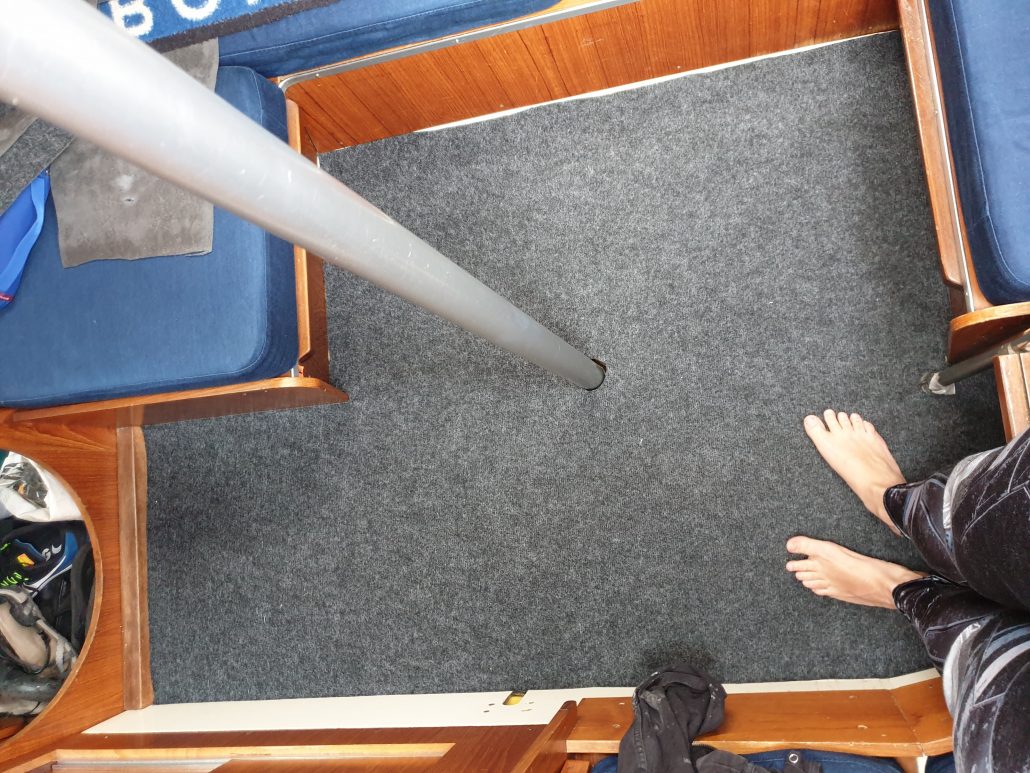
neuer Boden mit Teppich neuer Boden ohne Teppich


")

