
Tablesaw with Tilting Router Lift
Background
About two years ago I have modified a mini hobby table saw and expanded it with a new fence system made of wood in the workshop of the c-base. This project arose from the need to cut the parts for the vacuum forming machine. After the vacuum forming machine was ready and the first molds were created, we realized that we need a router table to produce molds for the vacuum forming machine. Furthermore someone donated a Flottjet tablesaw. From this, the idea was born to modify the left workbench to incorporate both the Flottjet table saw and a tilting router lift.
After some research, we decided that we wanted to build both the tilting router lift and the fence system for the table saw from plans designed by Matthias Wandel (woodgears.ca). Plans for the router lift are here, for the circular saw, we used on these plans. Construction began in January 2016
Funding and Participants
This project was funded by several members of c-base. We used the crowdfunding platform yeahletsdothat.com. This crowdfunding platform is currently being developed by @little_endian. In the future, this crowdfunding platform will be available to other groups and places (such as Hackerspaces) as a self-hosted alternative to the major crowdfunding platforms. This platform is not about financing products or startups, but it is made to manage fundraising for acquisitions and investments in smaller or bigger groups.
This project was conducted together with Susanna Huhtanen. All construction activities were carried out jointly, and all decisions were made together. We met every Wednesday and Friday in the evening and worked about 3-4 hours every day.
The oak boards we used were kindly provided by Timo, after they dried about 40 years in his shed.
Planning
As the workshop of c-base is quite small, it had to remain functional throughout the project. It followed that, we first had to prepare all the subcomponents before the final assembly was carried out. The subcomponents are: The tilting router lift, the Oak rails on which the fences ride and the tabletop.
Realization
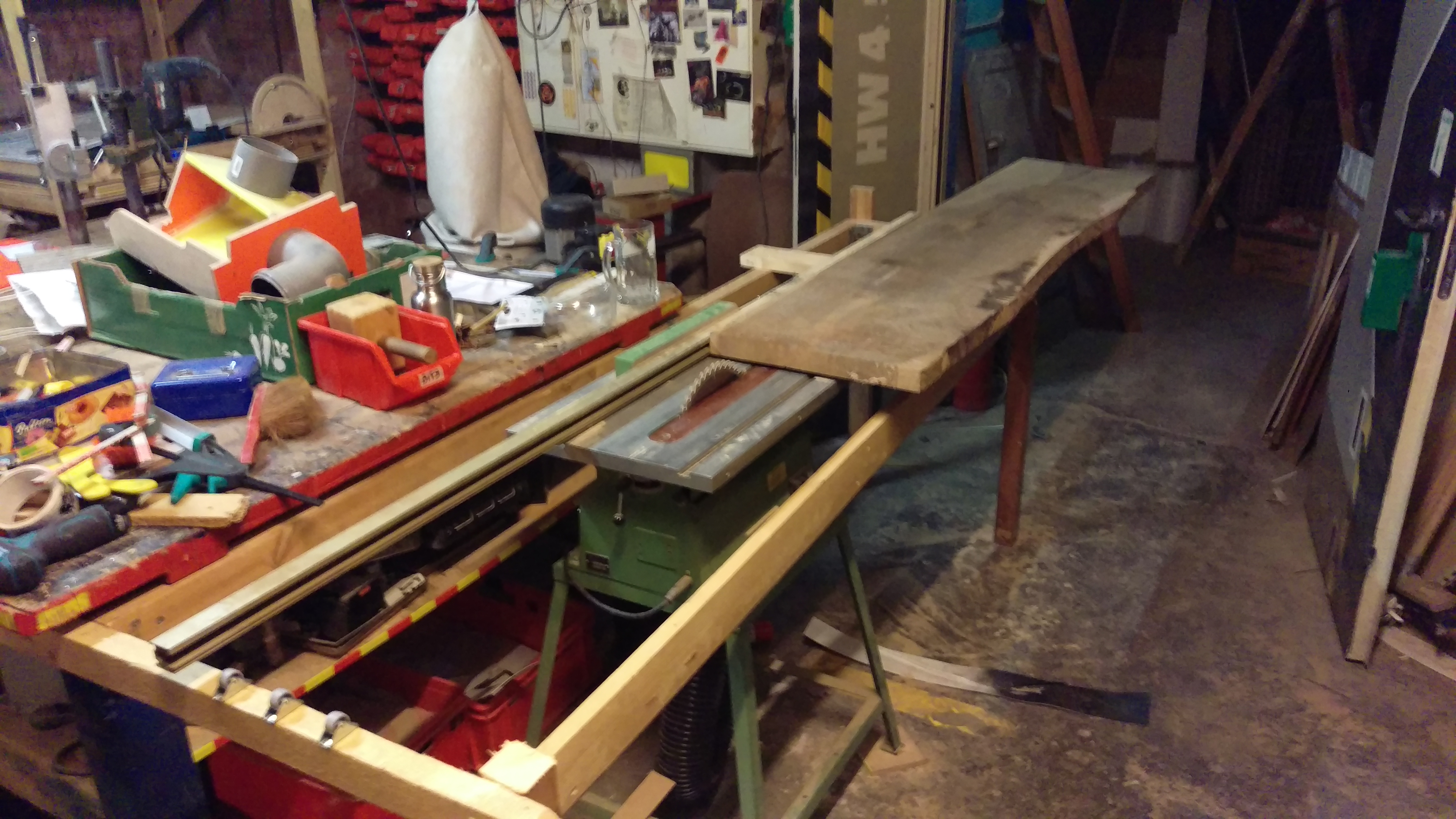
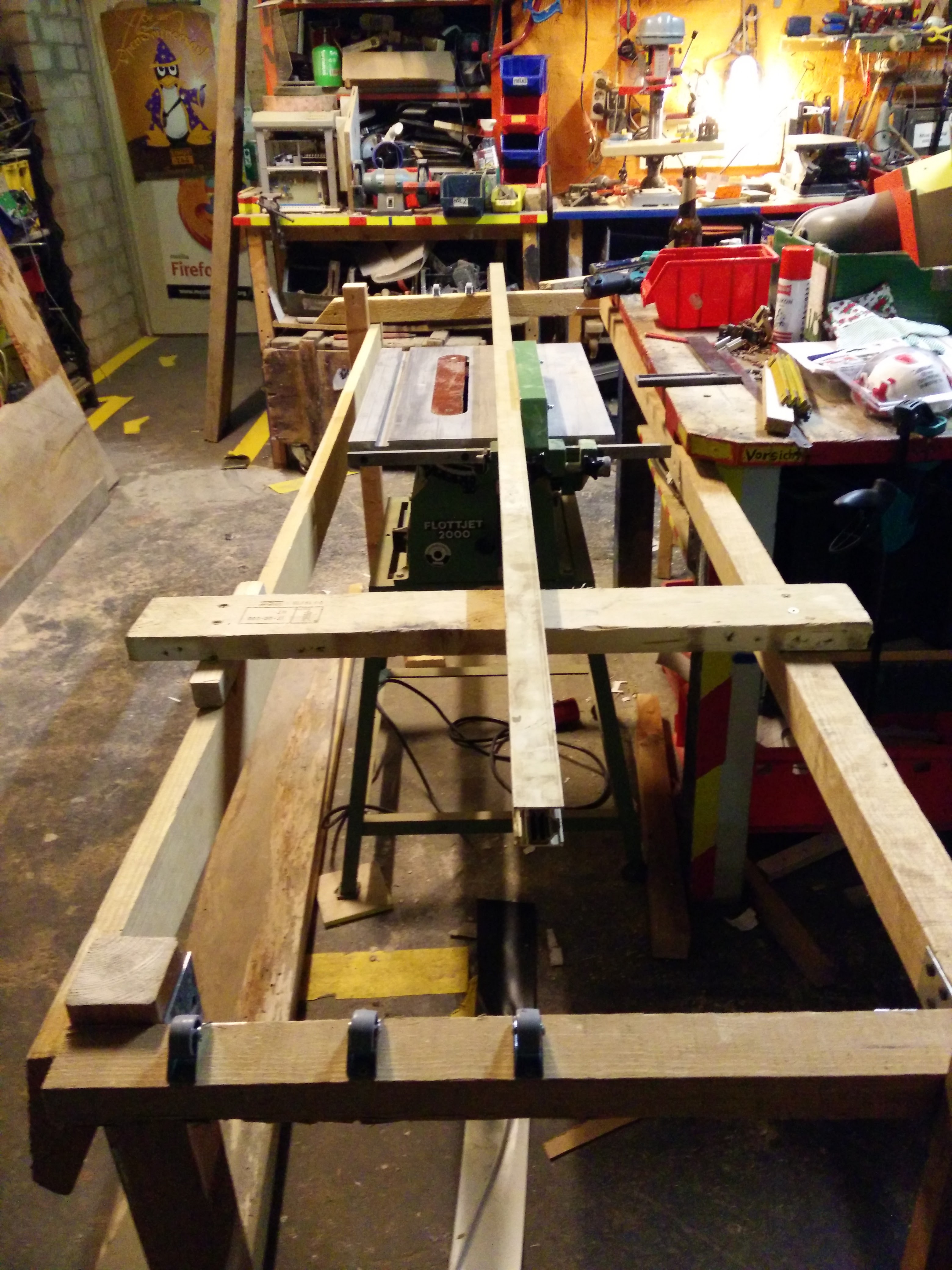 First we had to find a way to cut the large and very heavy oak planks lengthwise into boards. For this we improvised a scaffolding around the table saw on which we were able to move the oak planks by means of furniture castors. For several days, we cut the big oak planks into smaller and smaller pieces until we had removed all faults (cracks, knots) from the material. It has proven for us to be helpful to mark all known and visible cracks, knotholes and other unwanted interference with a thick red marker before we decided which boards we could get out of the raw planks.
Router Table
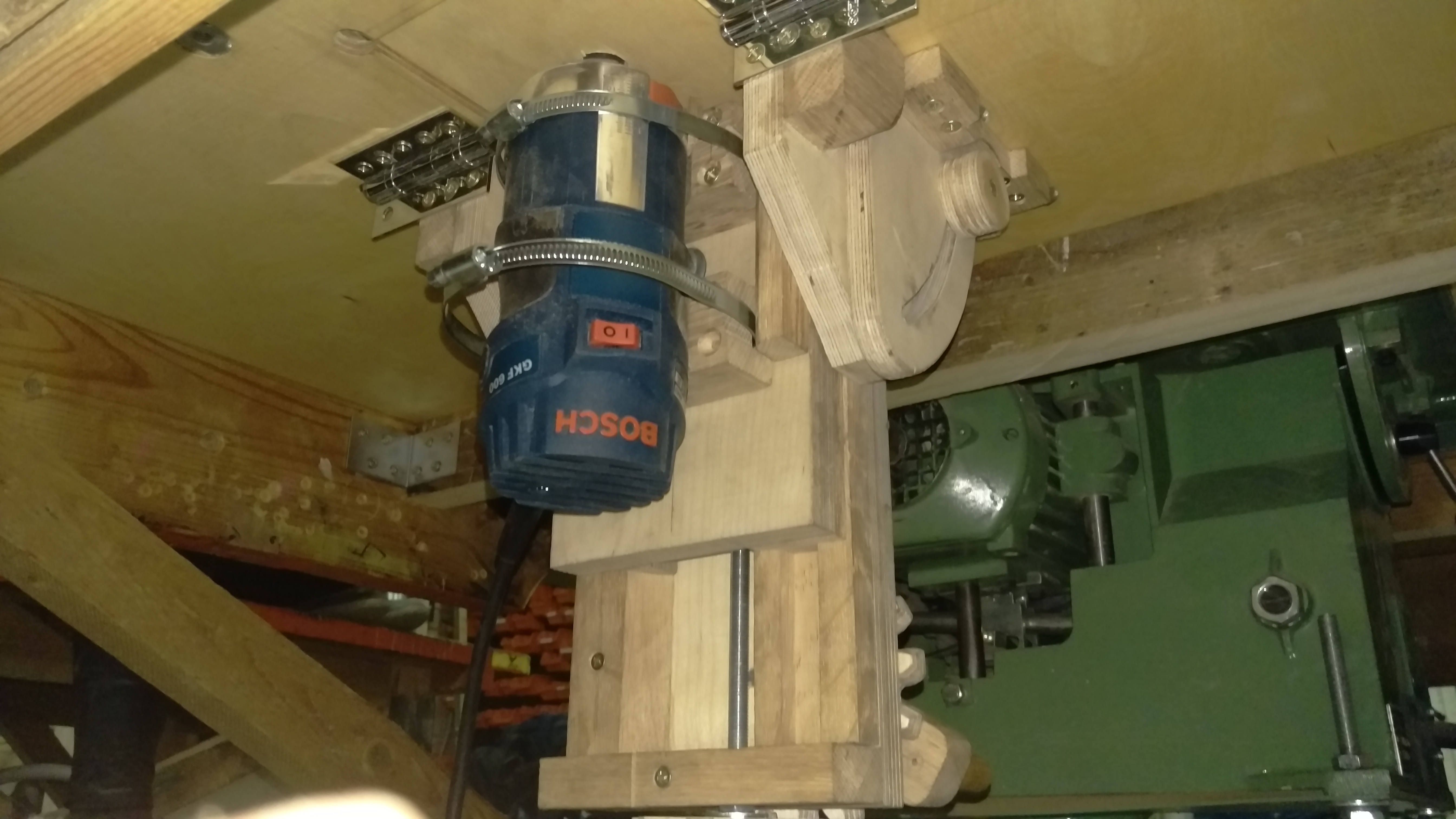
 The router lift is height adjustable and tiltable from 0-45 °. All router lifts that are commercially available are adjustable in height, but the possibility of a tilting router is an absolute premium feature within the commercial products. Usually the tilting feature comes at a premium of several thousand euros. The plans of Matthias Wandel are therefore not only a real cost savings, but also allow functions that we could otherwise not afford under any circumstances.
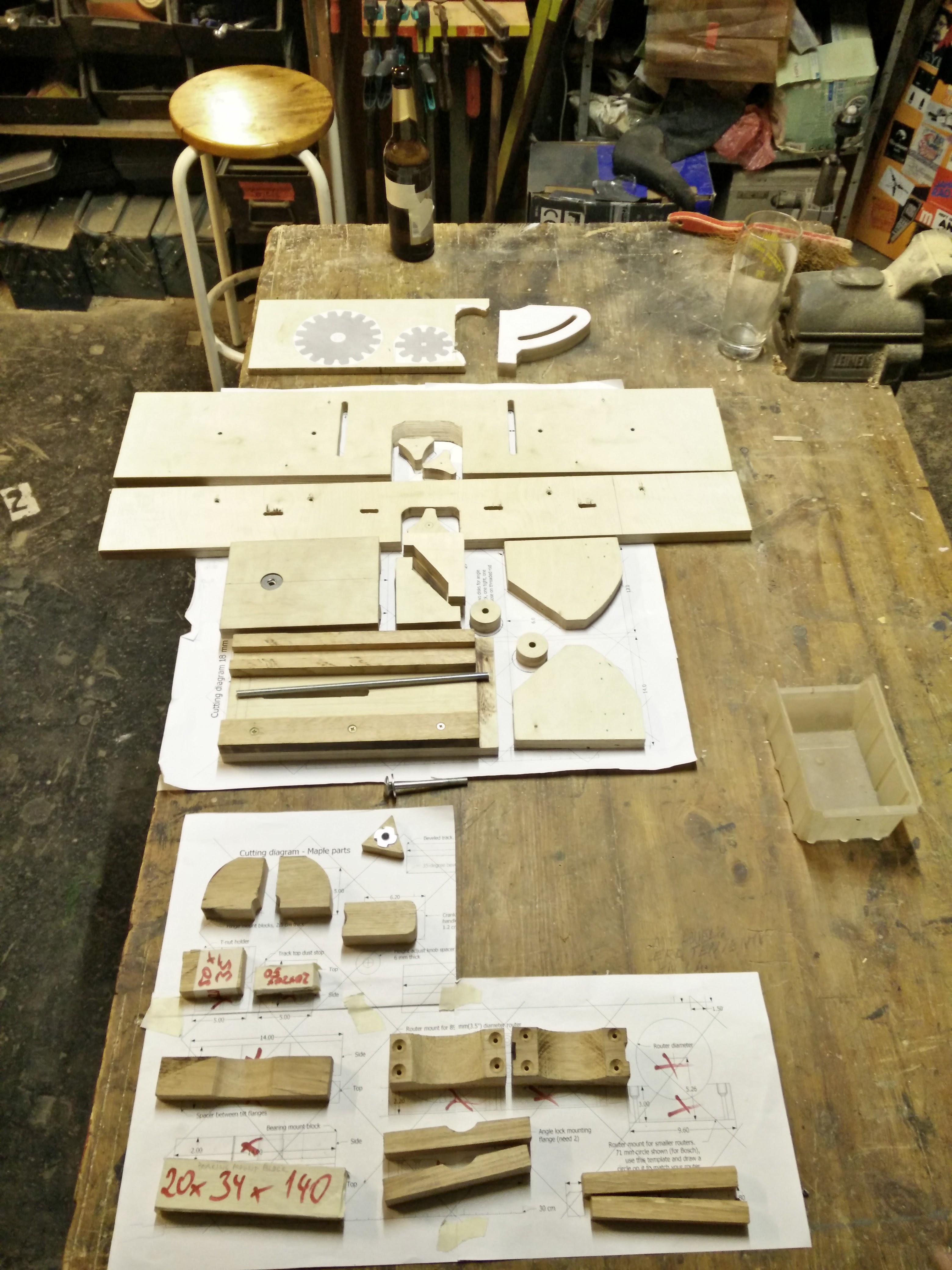
 From the smaller oak parts and several pieces birch plywood we then cut the many small blocks for the router lift. For several weeks, the blocks shrank in smaller and thinner pieces, a real progress was, apart from the sawdust production, hardly visible. The fence for the router lift seemed too small for the size of the workbench. Accordingly, we have strayed here from the plans and have constructed a slightly larger fence.
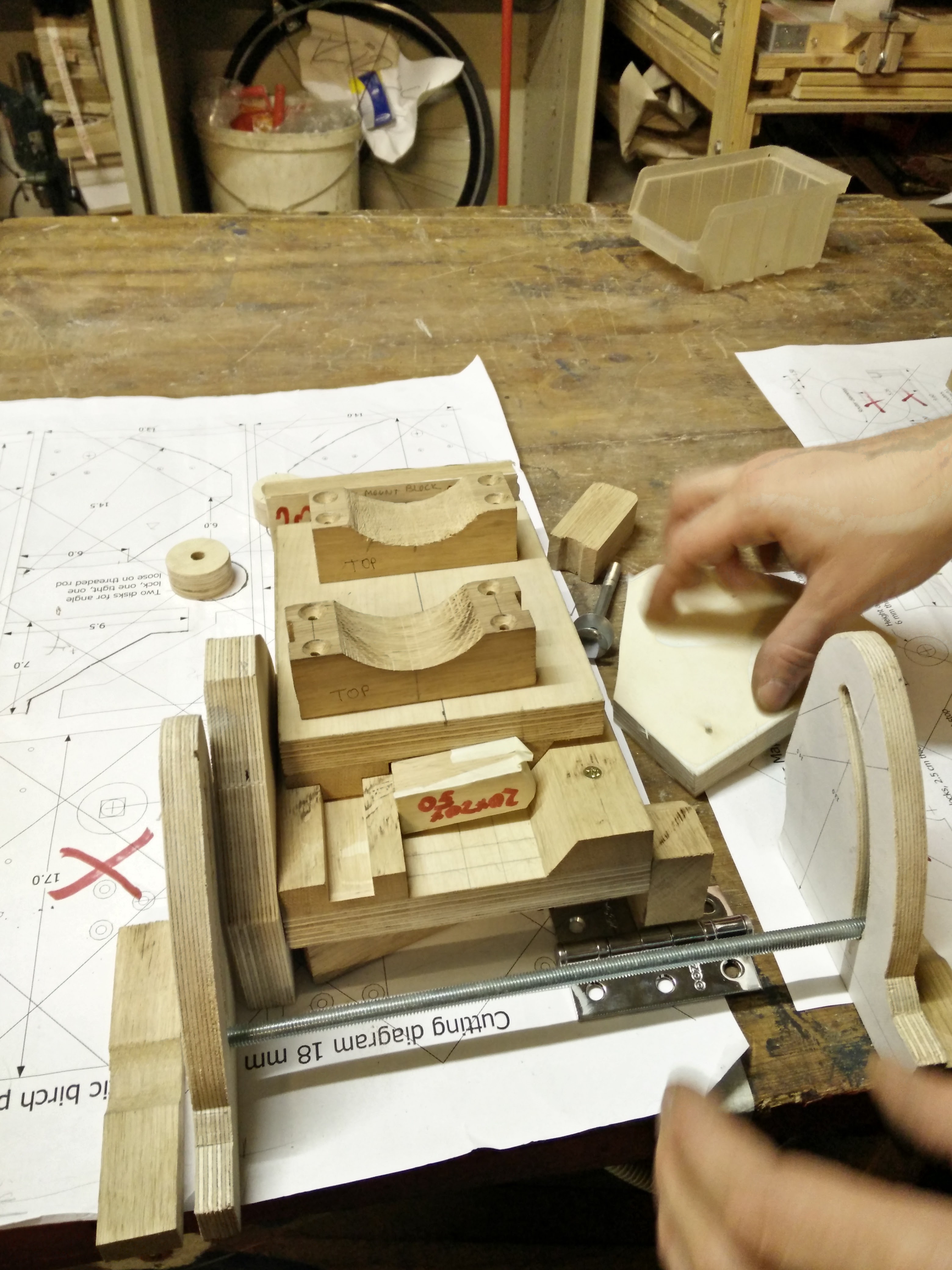
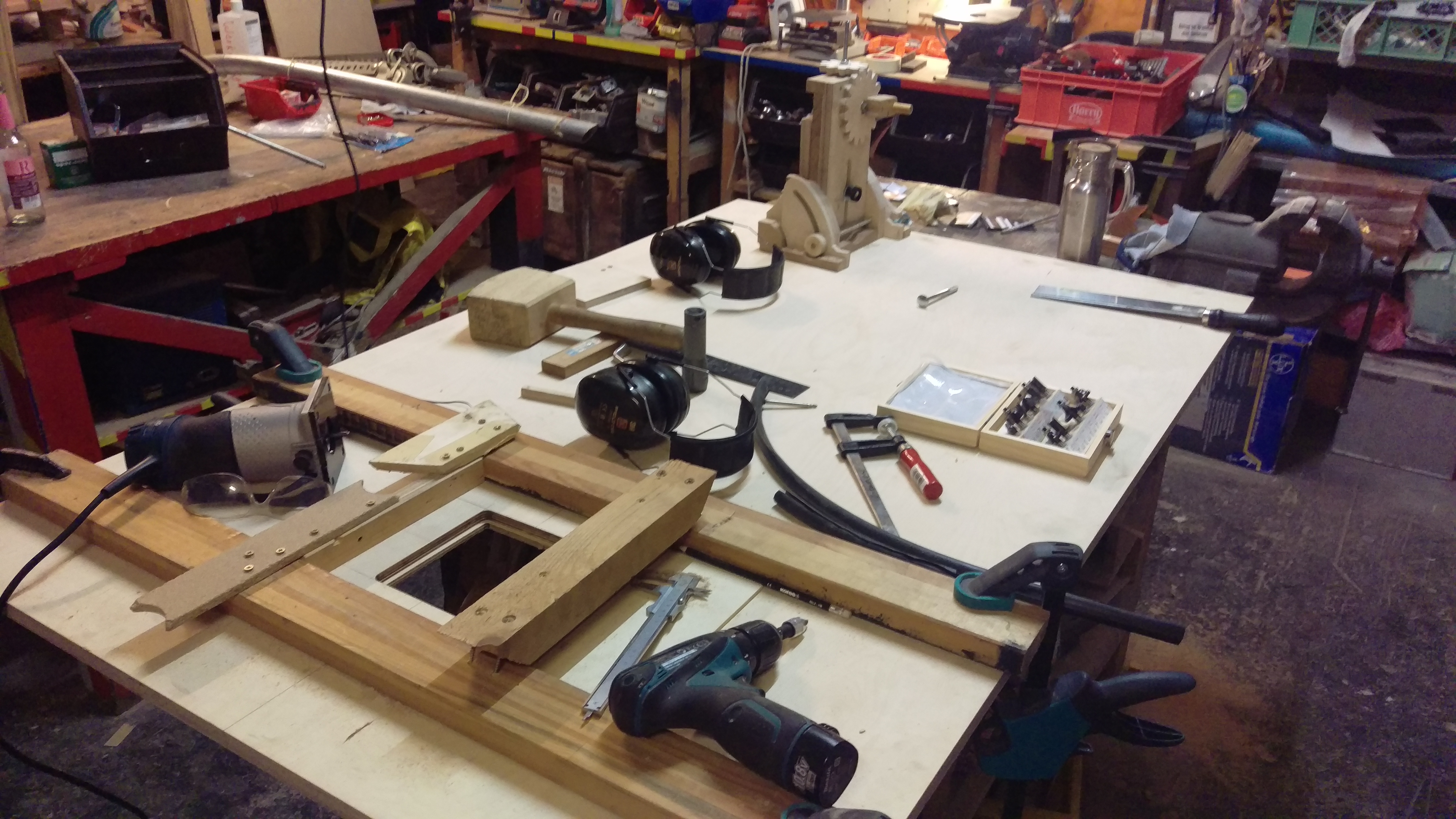 Finally the assembly of the router lift started. This took us at our pace several weeks and ended with the cutout in the table top for the router lift.
Router Fence
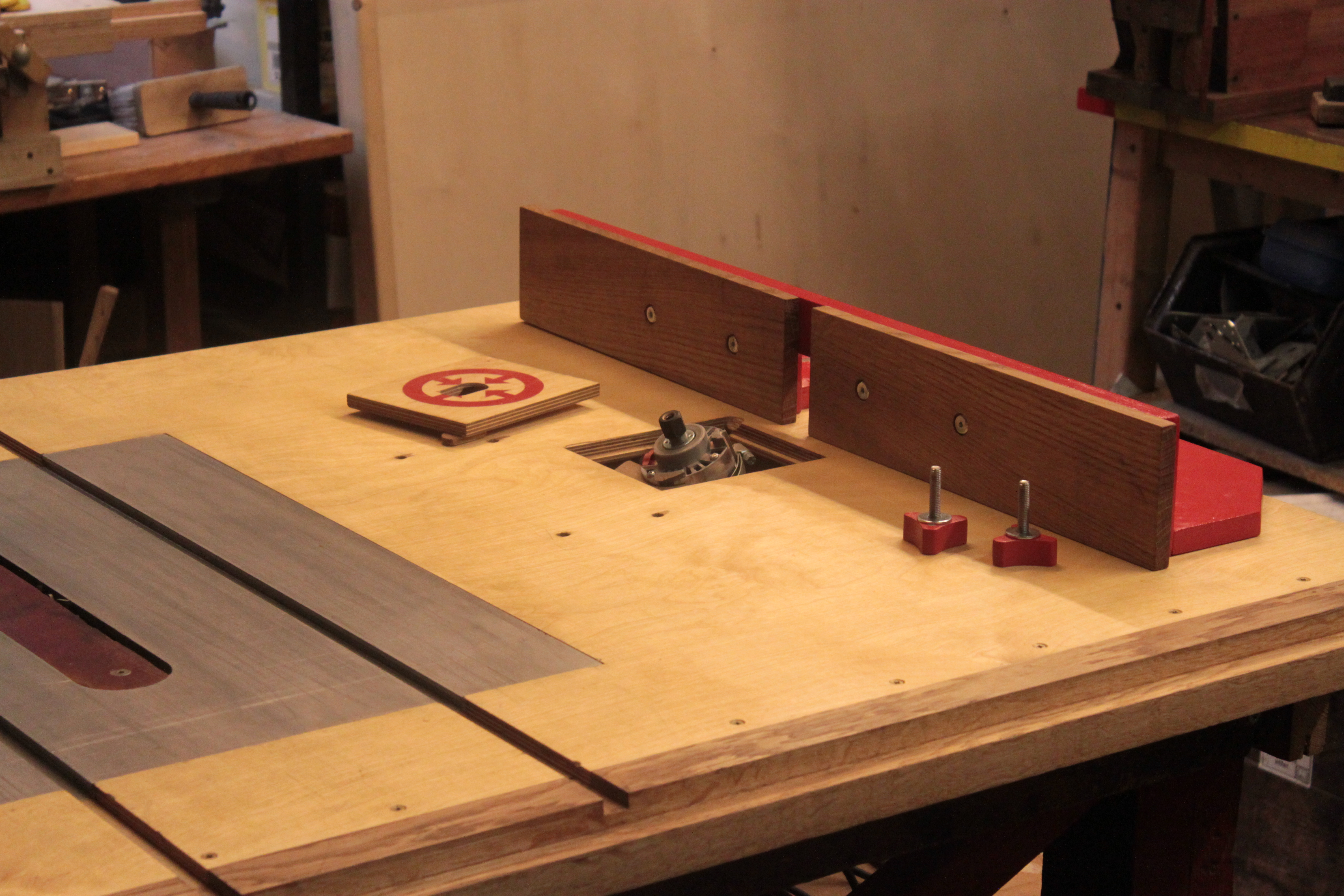
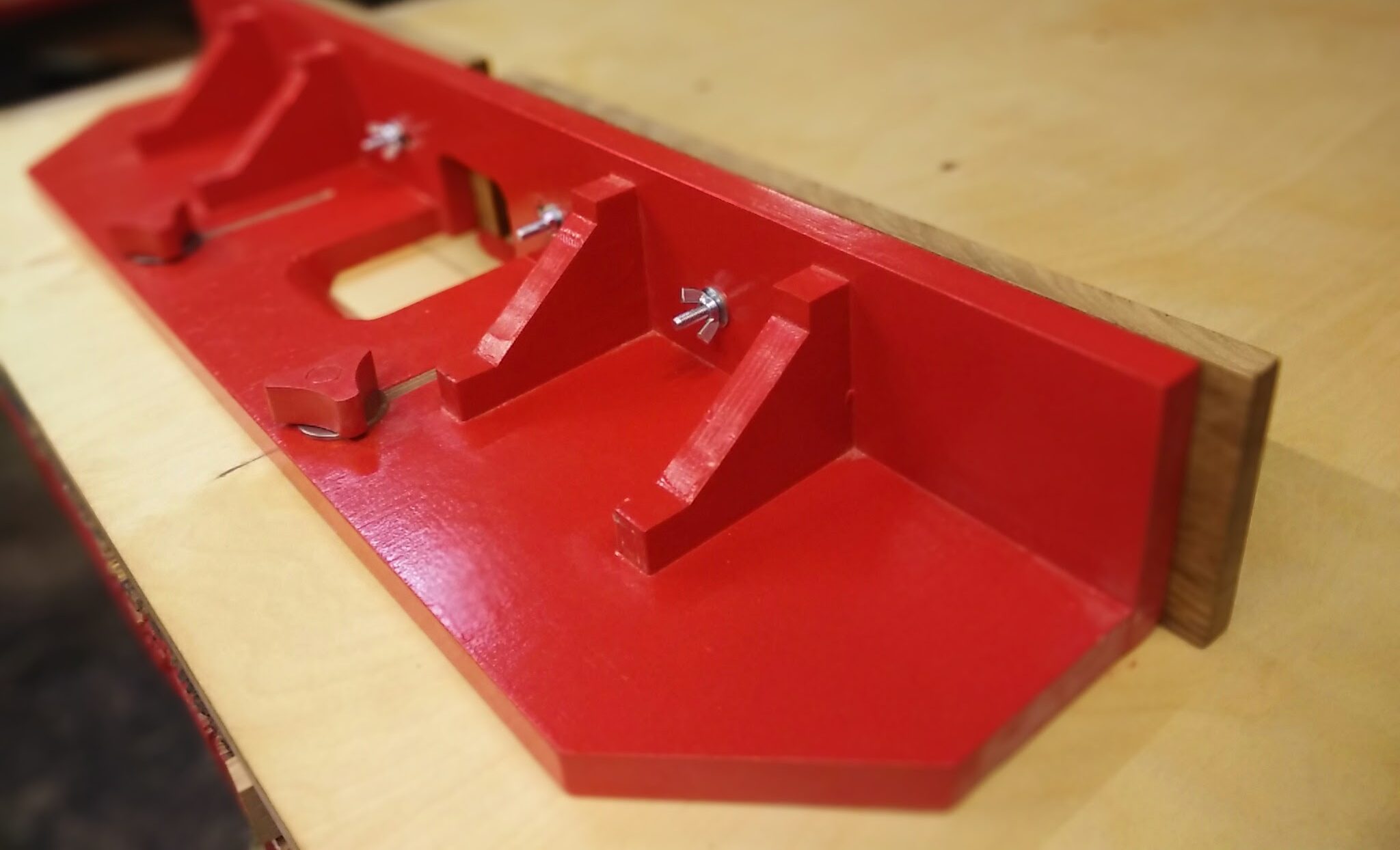 After the tilting router lift was completed, we made the fence for the lower cutter of 18mm birch plywood. The oak boards on the front are adjustable through slots and wing nuts depending on the width of the cutterhead. The fence itself is adjustable by means of elongated holes and screws with a knob. The large hole in the center was cut out to connect to our dust extraction there at a later stage. A router produces enormous amounts of very fine sawdust.
Parallel Fence
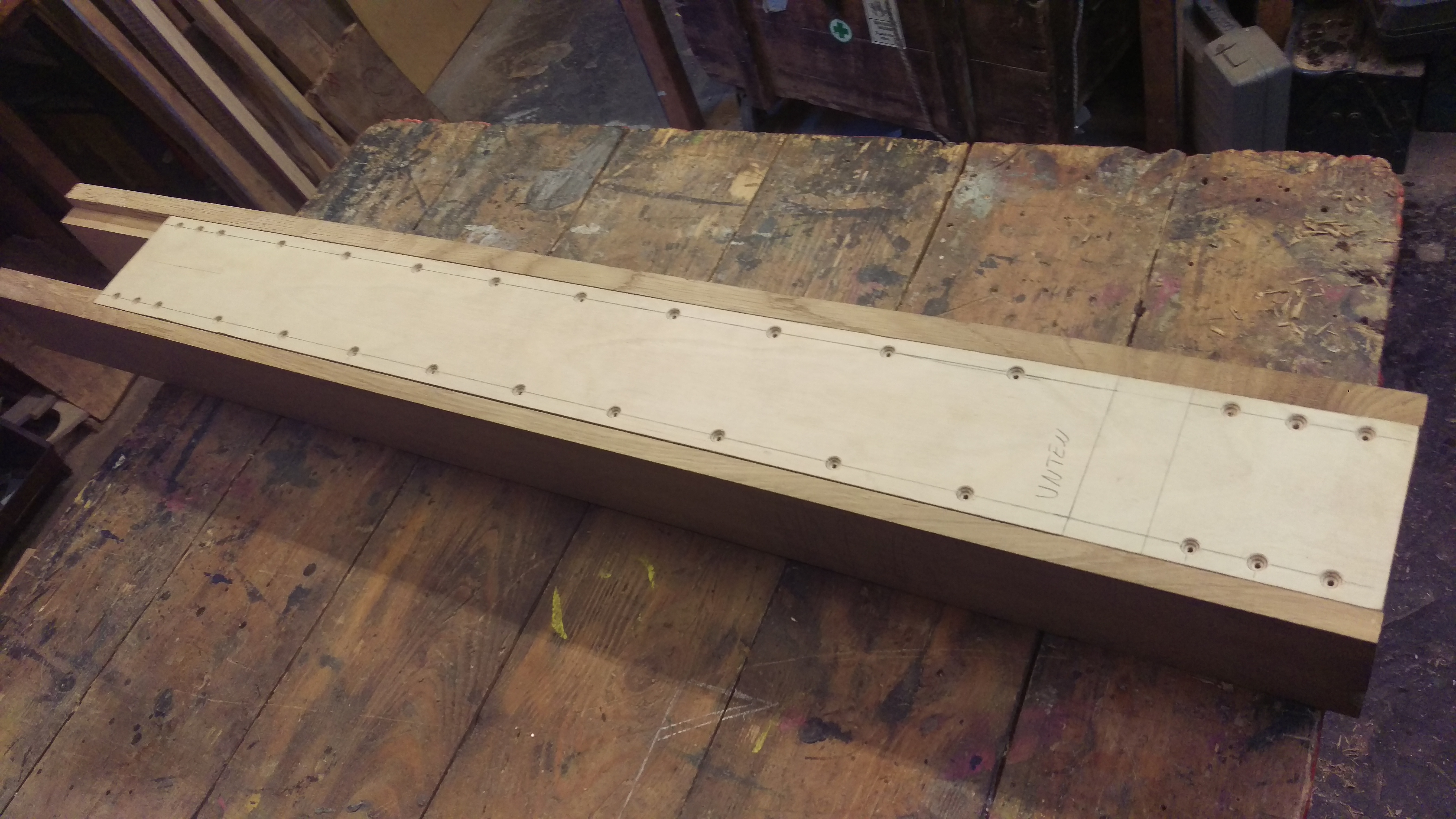
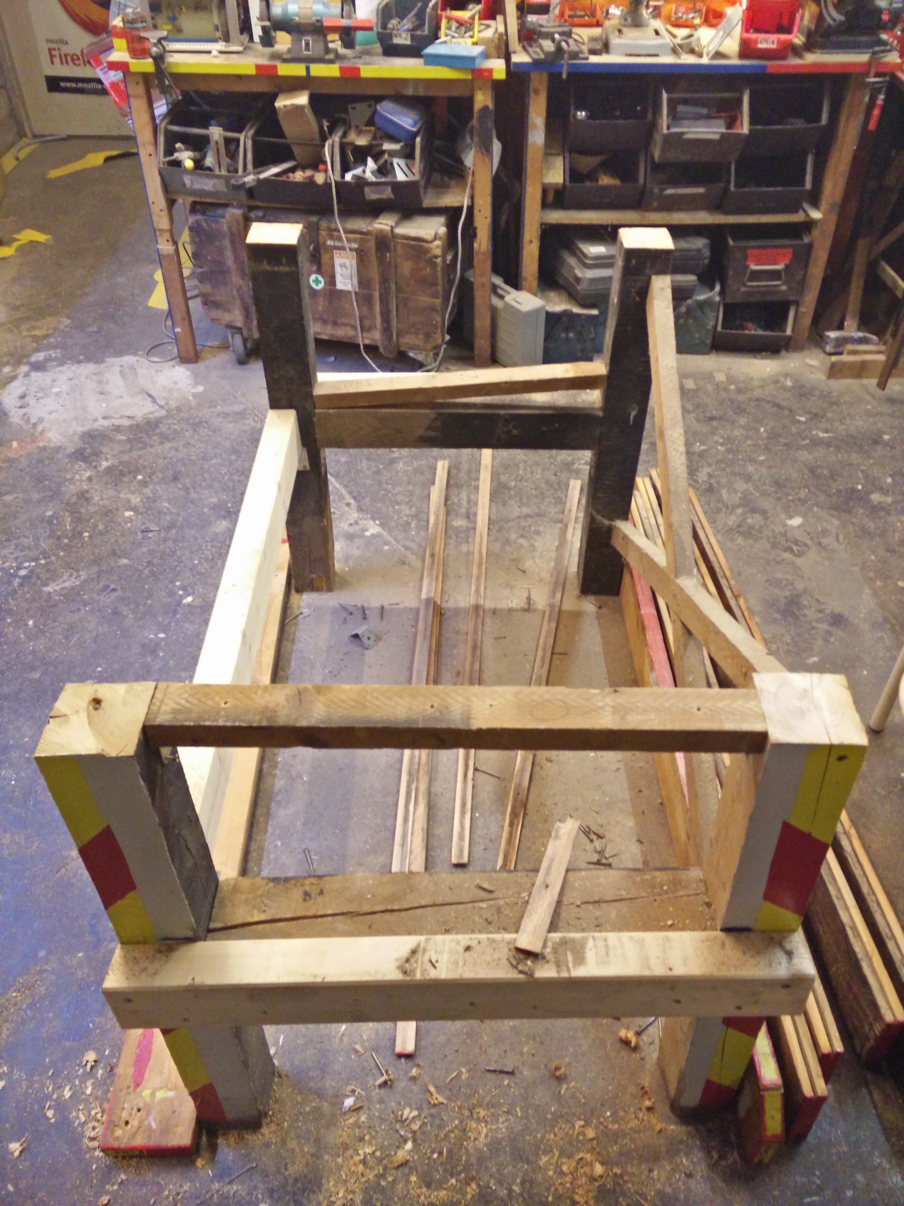
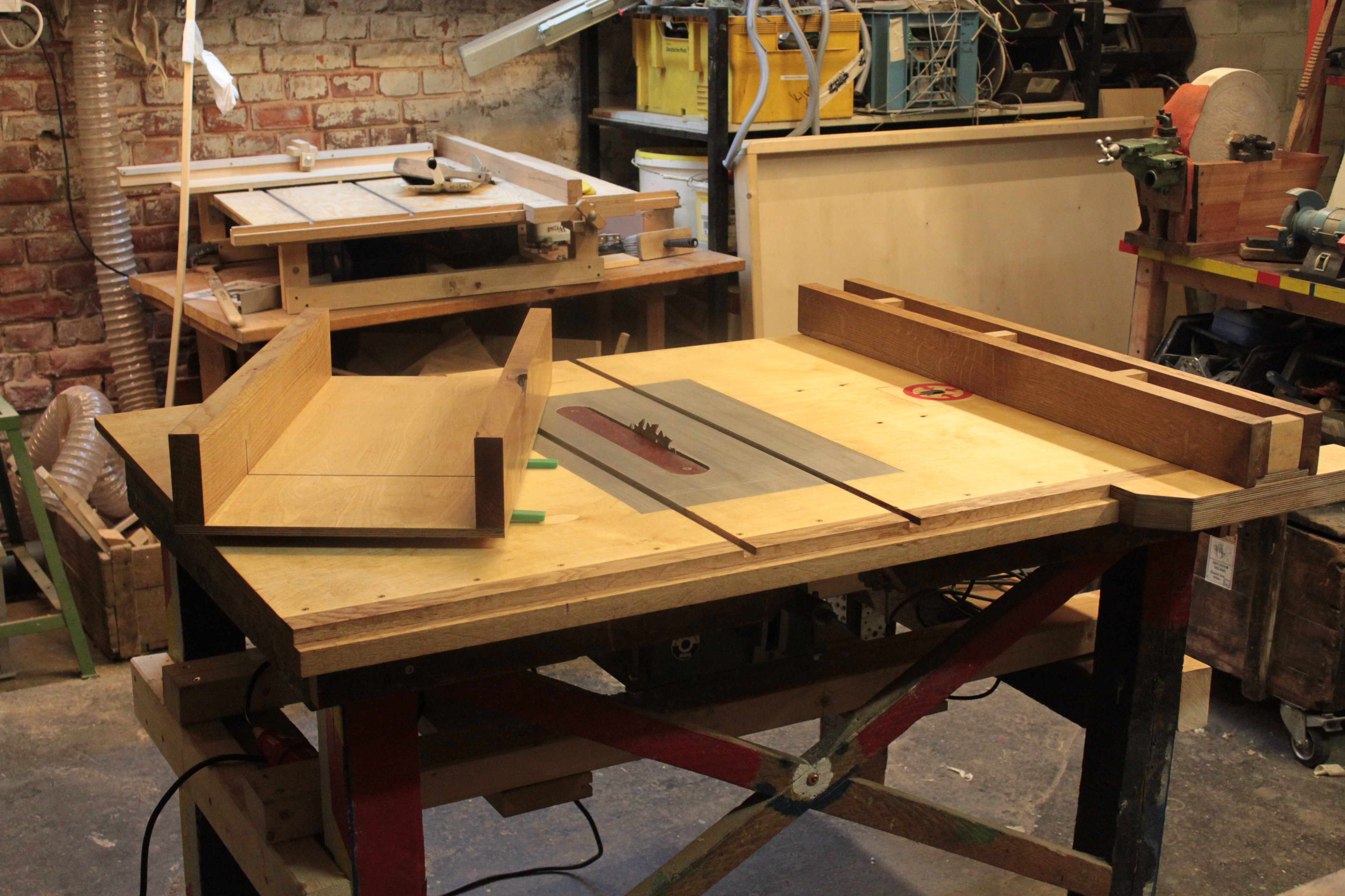
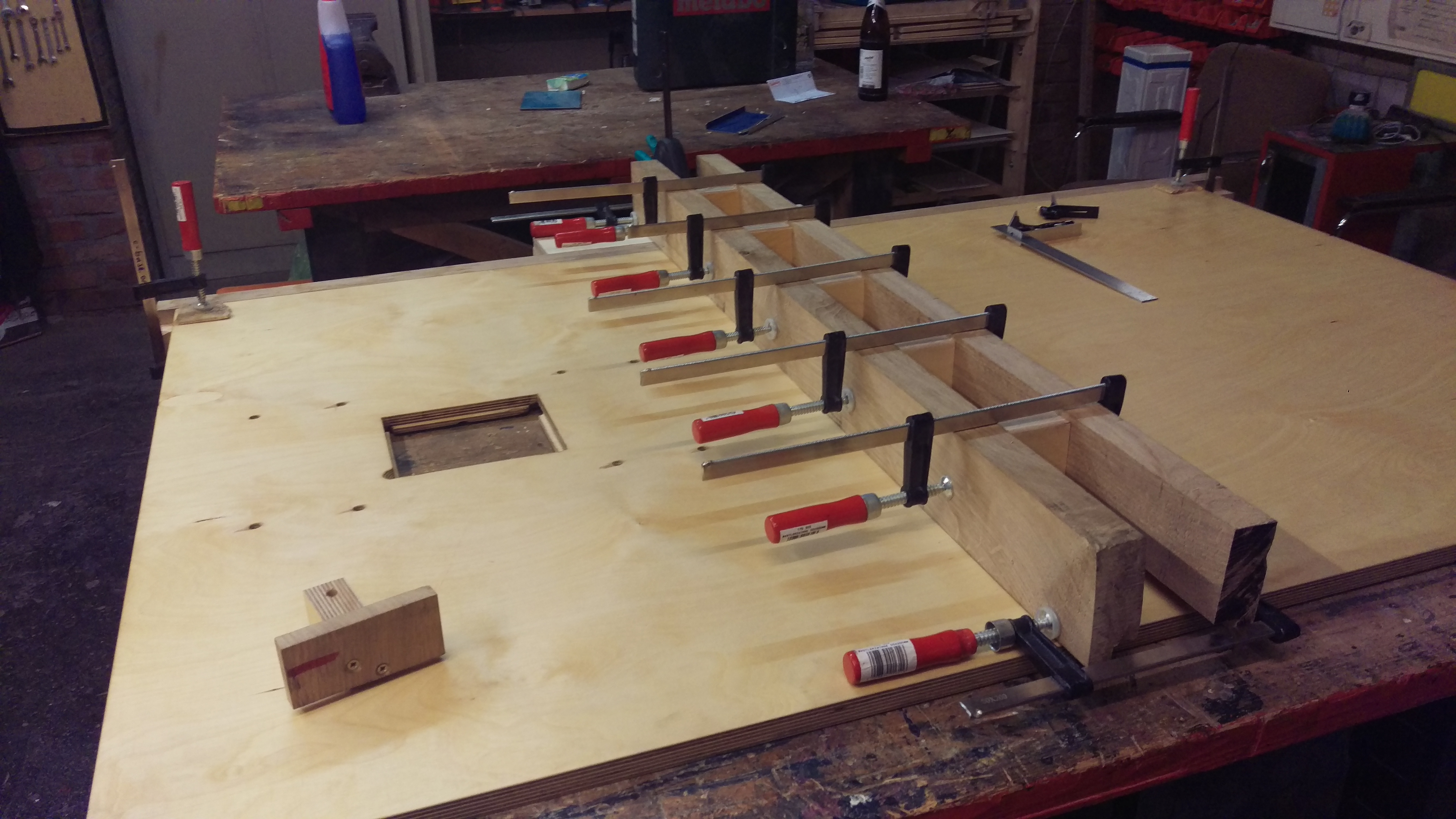 The parts for this fence were already cut and planed in advance during earlier phases of the project, so that only the assembly remained to be done. We decided to depart from Matthias plan and to make the fence from both sides usable. The sides were made of oak, the cross-braces between the Oak parts were made from 30mm birch plywood and the bottom plate of the fence was made of 12mm birch plywood. For this phase of the construction we placed the new, half-finished table top on the old planks that formed the old surface of the workbench. On some of these images the workbench can be seen in its old state of disrepair. The cross-braces are connected by wooden dowels with the oak planks. For this step I bought centering pins – a wonderful invention for exactly fitting dowels!
Final Assembly
 For the final assembly of all subcomponents Susanna and I reserved a full weekend, so that the workshop is blocked only for a few days by this project. First, we removed the old planks that made up the tabletop of the workbench. The bench was designed so that the table was also part of the structural design and stabilized the workbench. This is not optimal – actually one wants a skeleton that is in itself stiff and strong, on which then the tabletop is only secured against moving sideways. On the left is the substructure after we had mounted several thick beams for reenforcements. From the old boards of the tabletop, we made a ring around the upper ends of the table legs on which the new tabletop rests. Unfortunately we have no photos of this step.
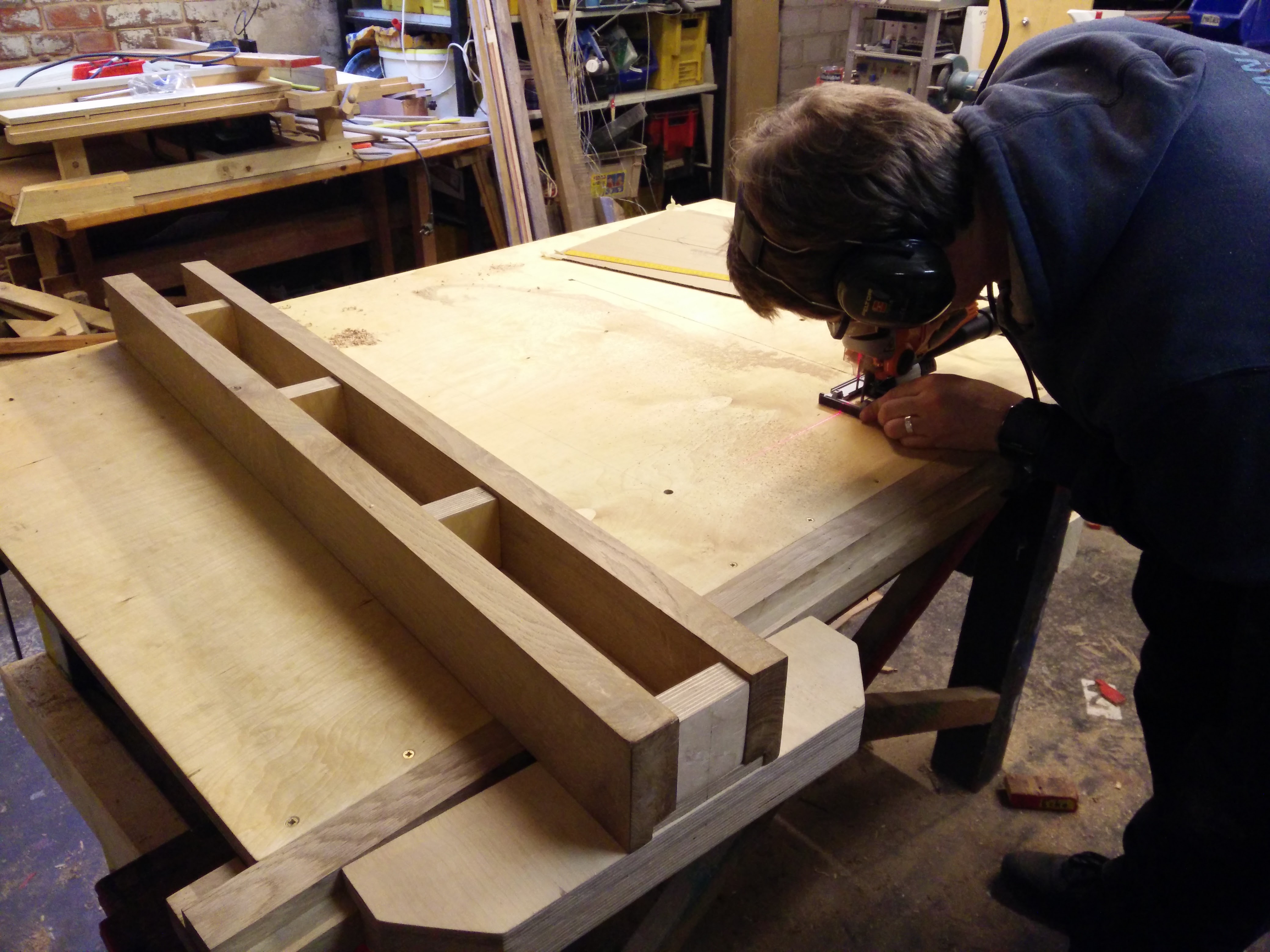
After the substructure was completed, the cut-out for the circular saw was cut with a jigsaw and then painstakingly altered with hand files until the circular saw fitted exactly into the hole.
During the final assembly we mounted two cameras and produced about 230GB FullHD footage. Currently this material is not sighted or cut. Once this has happened, the result will show up here on this blog.
Project Conclusion
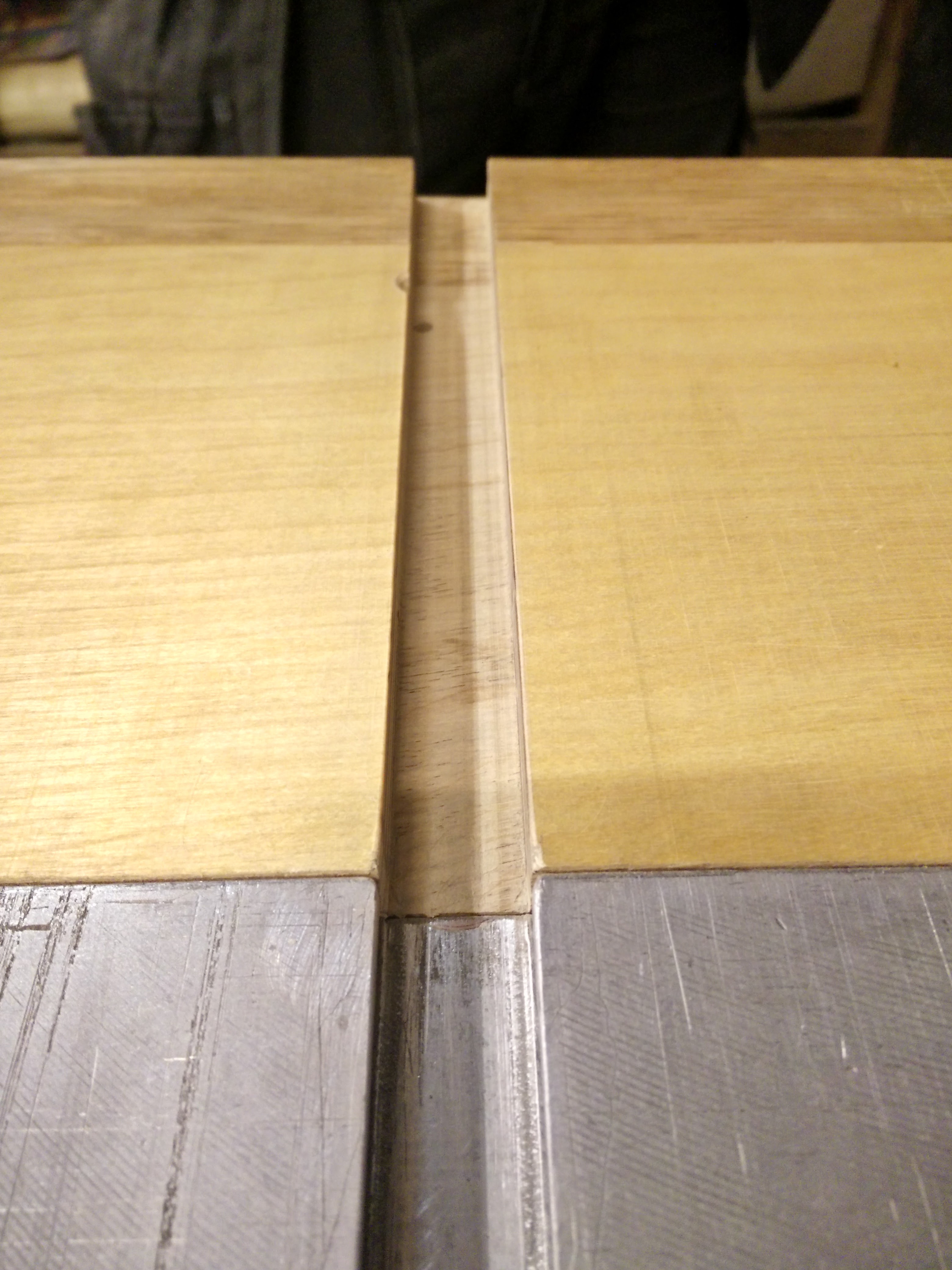 After the weekend of the final assembly there were still some minor things to do. The table top had to be fixed and in particular the slots for future miter- or crosscut jigs had to be extended into the new tabletop. Also, a cross cut sled for right-angled cuts was necessary and some parts hadnt yet received a good sanding and oiling during the building process.
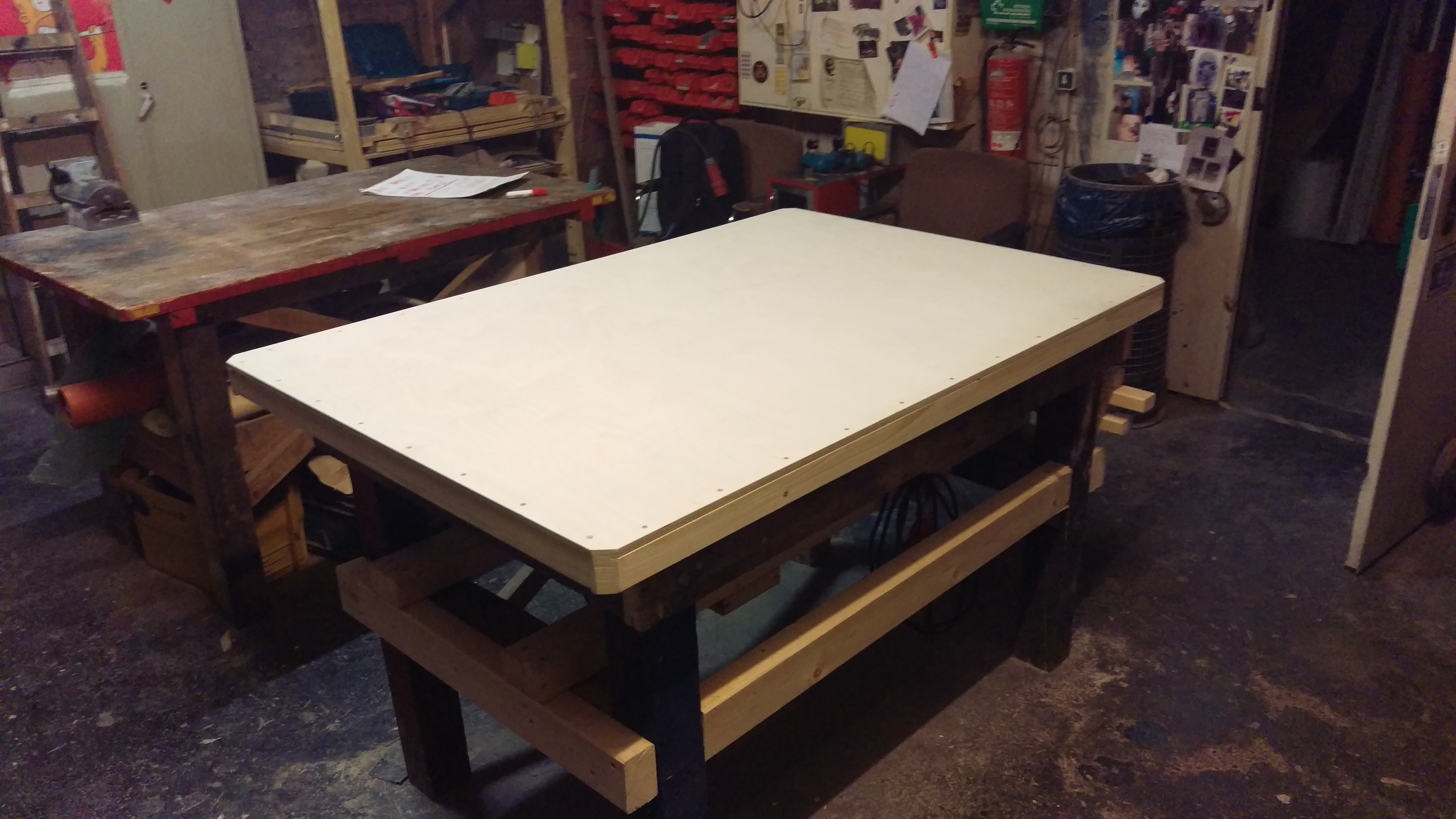 Finally we then constructed a cover from 12mm multiplex and some pine strips, which rests on top of the table top and protects the installation so that the beautiful surface remains intact as long as possible.
Project Results and Costs
 The project’s success has occurred, all planned features are implemented, tested and deemed functional. The total cost was about 80€ more than the estimated budget of 400€. These 80€ were needed for the materials to construct the protective cover, which was not initially planned.

")


